
738 views Yuda Electronic (HK) Technology Co.,Limited. 2018-07-13

Phone USB charger production design
In the figure, the resistor F1 of 1 ohm acts as a fuse, and the rectification is completed by a diode D1. After the power is turned on, C1 will have a DC voltage of about 300V, and supply current to Q1 through R2. The emitter of Q1 has R1 current detecting resistor R1. After Q1 is energized, the collector current will be generated through T1 (3, 4). At the same time, the induced voltage is generated on (5, 6) (1, 2) of T1, wherein the T1 (1, 2) output is rectified by D7, and C5 is supplied to the load through the USB socket; wherein T1 (5, 6) is rectified by D6 , C2 through IC1 (actually 4.3V voltage regulator), Q2 constitutes a sampling comparison circuit to detect the output voltage level;
Among them, T1 (5, 6), C3 and R4 also form a feedback circuit for the Q1 transistor, allowing Q1 to operate at high frequencies and continue to supply power to the T1 (3, 4) switch. When the output voltage rises due to light load or high power supply voltage T1 (5, 6), IC1 sampling comparison leads to Q2 conduction, Q1 current decreases, and electrode current decreases, load capacity becomes smaller, resulting in lower output voltage; When it is lowered, Q2 is cut off again, the load capacity of Q1 becomes stronger, and the output voltage rises again; this will automatically adjust the voltage.
Although there are few circuit components, it is also designed for overcurrent overload and short circuit protection. When the load is overloaded or short-circuited, the electrode current of Q1 is greatly increased, and the emitter resistance R1 of Q1 will produce a higher voltage drop. The high voltage generated by this overload or short circuit will conduct between Q2 and R3, so Q1 will stop. Prevent overload damage. Therefore, changing the size of R1 can change the load capacity. If the required output current is small, for example, only 5V100MA is required, the resistance of R1 can be increased. Of course, if you need to output 5V500MA, you need to reduce R1.
What is the role of C4, R5, D5? The T1 transformer is an inductive component. When Q1 is turned off, it produces a very high voltage on the electrodes. This voltage can be as high as 1000 volts or higher, which will damage Q1. Now there is switch D5, this voltage can charge C4, C4 can be discharged through R5 immediately after charging, so Q1 will not be damaged by the high voltage of the electrode. Therefore, if these three components are damaged, Q1 will be very dangerous and will most likely be damaged.
1N4007 is a low frequency diode, FR107 is a high frequency high voltage diode, and 1N5819 is a low voltage high frequency Schottky diode. (FR107 can replace 1N4007, but vice versa; 1N5819 cannot be replaced by other diodes. The turn-on voltage of 1N5819 is very low. Therefore, the low-voltage rectification efficiency is very high. If other diodes must be reversed, the efficiency will be low.)
Cell phone accessories wholesale business can get high profits. But the market is fierce. Big bra...

Does fast charging reduce phone battery life? In order to allow everyone to understand this matt...
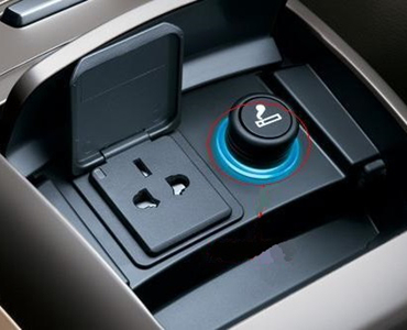
How to install the car charger: 1. Insert the USB power adapter into the car cigarette lig...
